Here’s the X102BA taken from brand-new-in-box down to most of its component parts.
We start with the unboxing:


Looking around the case, there’s a reasonable selection of ports. On the left side, VGA, HDMI, charger, and a single USB3 port.
On the right, a pair of USB2 ports, the mic/earphone socket, Kensington Lock, and ethernet – with a peculiar sprung flap to hold the RJ45 lug.


The back and underneath are unremarkable:


Then the disassembly, all of which was done using a PH0 (Phillips) screwdriver, and a plastic spudger. It’s easy to do if you take your time.
All of the screws are the same head, the only differences being that 2 different lengths of screw are used. The machine ships with a plastic blank in the SD card slot. This must be removed otherwise it stops the case from coming apart.
The only obstacle to getting the case open, is 3 hidden screws. The screws hiding under the rear pair of rubber feet were predictable; the one under the serial number label less so.

Once all 6 screws are out, it’s simply a case of gently inserting the spudger at one corner (beside the LEDs seems easy) and prizing the two halves of the case apart.

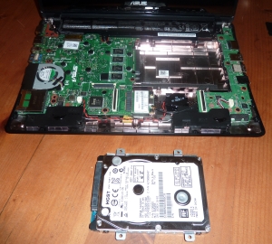
A few things are immediately apparent:
- There’s a fan
- The RAM is soldered, so can’t be upgraded
- There’s only one Mini-PCIe slot, which contains the WiFi card already
- The drive is a standard SATA disk and totally upgradeable
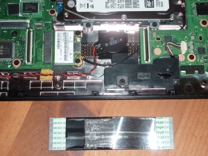
Before we progress, we need to remove the keyboard/trackpad assembly, so that we don’t damage the cables. There are two cables, each goes to a different type of ZIF socket on the motherboard. The wider ribbon cable goes to a socket with lugs which lever gently backwards to release the ribbon. The narrow one goes to a tiny socket which has lugs which flip upwards to release the cable. Both are easy with the spudger and require little force.

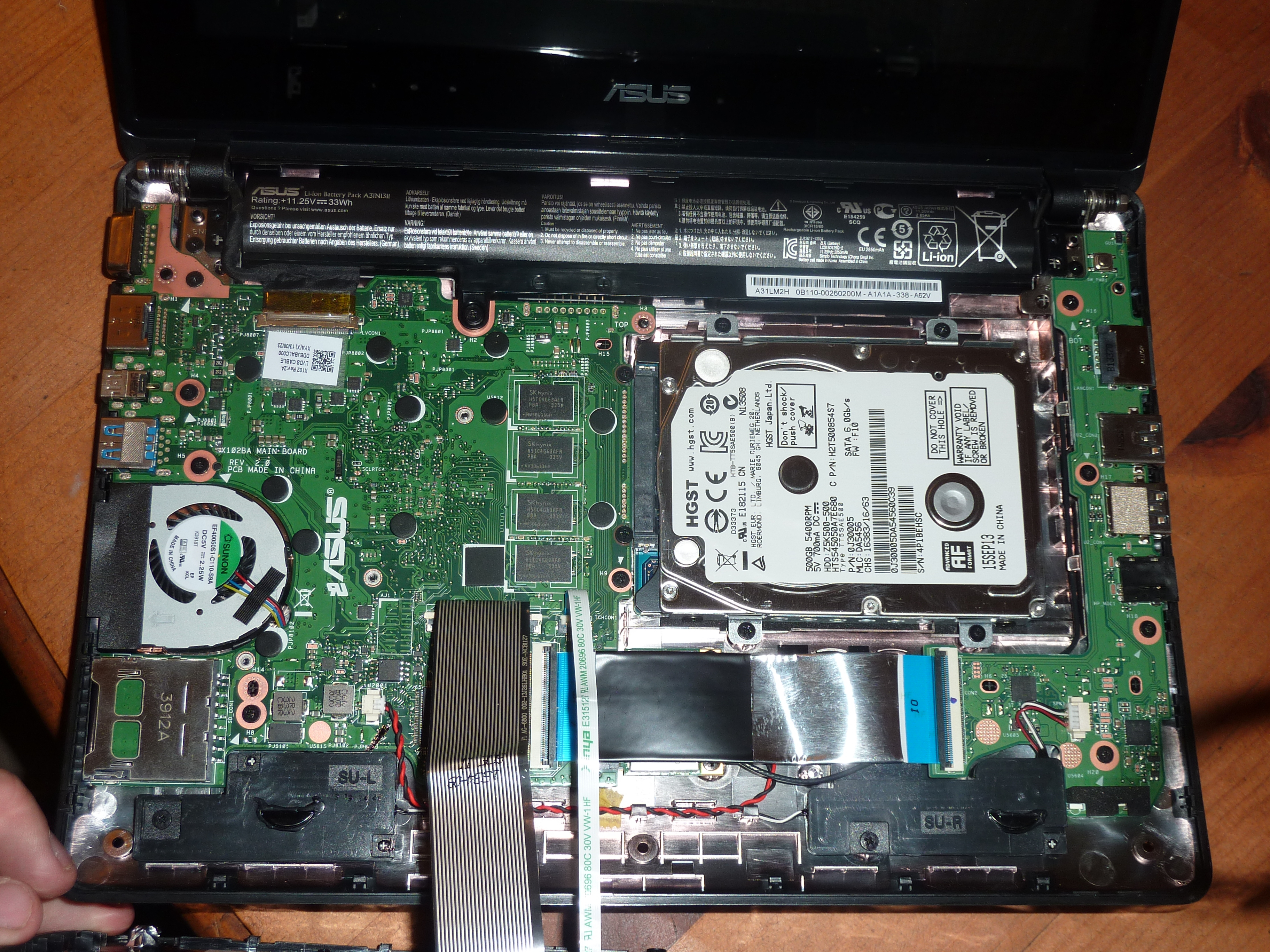
Now the keyboard is removed, we can relax a bit and have a close look at that soldered RAM and the disk. Note that there are 4 more RAM chips on the reverse side of the motherboard (see below).


There’s a large, silvered ribbon cable connecting the motherboard on the left, with the daughterboard on the right that holds the LEDs and right-hand set of ports. It’s also hiding the mini-PCIe wireless card. It comes out very easily by gently easing the two ZIF sockets open:
This gives us a closer look at the wifi module; what a shame they only connected a single antenna. There’s clearly room for a larger and more capable module – but sadly no more slots:


Removal of the disk is as easy as it looks – undo 4 screws and pull very gently:
With the big ribbon cable removed, the daughterboard can be unscrewed:

Giving a closer look at the sprung cat5 socket:

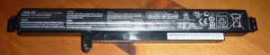
We can now undo one screw and pull the battery out. There are no cables connected to it, it simply rests against connectors on the motherboard. It’s 11.25V 33Wh.
We can now remove the last few screws and pivot the motherboard out, to see the underside. Note RAM chips and fan.


and that’s it. Hope someone finds this useful.


You must be logged in to post a comment.